Keyboard Shortcuts
Likes
- Pcbgcode
- Messages
Search
|
I'm having great success with Eagle 9.2.2. I make small boards for through-hole components and, so far have been able to get everything on a single layer without jumpers but next project will require them.
I do an outline on the Milling layer and the router4 cuts out the board. I have NOT been able to get a 1/4 inch hole recognized and cut however.? It doesn't get picked up by PCB-GCODE and doesn't get cut.? I use the Circle command in Draw to make the hole. I've put it on the milling layer and alternatively on the Dimensions layer, but no-joy. It possible that I don't have Eagle set up right? What would you look at if this was your problem? john |
|
You may remember a struggle I was having with some traces shorting out.? As it turns out, I had converted a library file for a 28 pin DIP from having little round pads to the elongated type which I find easier to solder.? And of course somehow when I loaded it, Eagle thought it still had the smaller pads and although the traces cleared them, some of them ran right through the pads.
I'm not sure how, but this doesn't seem to happen anymore and I can pretty much etch a board without any manual trace adjustments. I am puzzled by another effect I'm getting. I like to spot drill pads and set the spot-drill depth to .011, but they get spot-drilled to .075 which is where I have the drill depth set. What am I missing here. john |
|
[pcbgcode:master] reported: Use small endmill to mill holes of various sizes
#github
[email protected] Integration
[pcbgcode:master] New Comment on Issue
By :
I am after the development of my own economic ATC, so it is also a solution that interests me. With hole diameter and milling data, it is feasible to make larger diameter holes than the tool. I have made a complement for helical descent in BCNC, with help I think it can be implemented directly in Pcbgcode |
|
[pcbgcode:master] new issue: Milling with 3 bits
#github
[email protected] Integration
[pcbgcode:master] New Issue Created by :
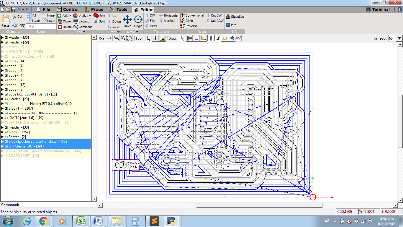
I John, here I show you what I have done using 3 bits: 0.10 - 0.7 - 3.0 and here I have implemented: I have run pcb gcode 3 times, changing the dimension of the tool to 0.10, 0.8 (0.7 + 0.1) and 3.0.
In BCNC I have enlarged the traces of 0.1 in +0.7. Intersect between traces of 0.7. Then I made a difference with the traces of 0.10. To the result perform pocket operation with 0.10
Between 0.7 and 3.0 the algorithm would have to be repeated (I have done it manually)
Perform a pocket operation on the dimensions of the board for bit 3.0, subtract the traces of 3.0 so that they do not enter it
|
|
Updates to Github
#github
[email protected] Integration
[pcbgcode:master] New Issue Created by :
I John, here I show you what I have done using 3 bits: 0.10 - 0.7 - 3.0 and here I have implemented: I have run pcb gcode 3 times, changing the dimension of the tool to 0.10, 0.8 (0.7 + 0.1) and 3.0.
In BCNC I have enlarged the traces of 0.1 in +0.7. Intersect between traces of 0.7. Then I made a difference with the traces of 0.10. To the result perform pocket operation with 0.10
Between 0.7 and 3.0 the algorithm would have to be repeated (I have done it manually)
Perform a pocket operation on the dimensions of the board for bit 3.0, subtract the traces of 3.0 so that they do not enter it
bit 3.0
|
|
Re: Intelligent milling with 4 bits
#development
He escrito en su sitio de Github lo que creo que sería bueno obtener
? |
|
[pcbgcode:master] reported: Use small endmill to mill holes of various sizes
#github
[email protected] Integration
[pcbgcode:master] New Comment on Issue
By :
This is good. I think a good option is to choose one (or more than one) tool diameter to drill, and generate a helical descent of the target radius |
|
Intelligent milling with 4 bits
#development
Hi, I'm new here, I think it would be a good option. Can you implement it? I have little knowledge of programming, although I have advanced with a complement to implement it in BCNC, but it is not the best option.
I hope you see it as viable or help you as much as you can.
I saw you move to Github.
Congratulations on your software!
? |
|
Re: How to etch a powerplane with pcb-gcode?
#etch
Or,
Skip the, 'remove all the copper mentality'! With completely uncoated boards you only need 50mil spacing for 300V.? If the board is coated with about anything you need even less - only 16mil. |
|
Re: How to etch a powerplane with pcb-gcode?
#etch
Christian Robert Adzic
John & Bruce: On which layer should I draw my polygon? If you say I should name my design xxx than you think the file name should be the xxx name?
From which xxx should I delete? From the xxx or xxx-cutout?
|
|
Re: How to etch a powerplane with pcb-gcode?
#etch
Milling out large areas between high voltage traces. Do your normal design and route using the name xxx, then - For areas to be removed draw a polygon between the traces (any shape).Right click on each milling area polygon's boundary and select 'Properties' Choose 'Polygon Pour' = cutout. When the design is complete copy it and rename the copy to xxx-cutouts. Delete from xxx - Milling Polygons (except ground plain) Milling Boundaries Delete most things from the xxxx-cutouts, except - Board Boundaries Milling Polygons Milling Edge Lines Etch xxx Surface end Mill xxx-cutouts Boundary Mill through xxx-cut throughs I haven't tried this, but it should work. When converting xxx-cutouts to gcode you will probably need a new configuration for the width of the end mill to stay-inside-the-lines. bye. On Mon, 26 Nov 2018 at 07:26, Fred Genius <fredgenius@...> wrote:
|
|
Re: How to etch a powerplane with pcb-gcode?
#etch
You could look into doing a polygon with a crosshatch fill pattern, with the pattern spacing smaller than your endmill size. Been a while, so I’m a bit rusty on the details.
toggle quoted message
Show quoted text
You could also just draw a grid or stripes on the milling layer. Regards, JJ From:?Fred Genius <fredgenius@...> Reply:?[email protected] <[email protected]> Date:?November 25, 2018 at 3:26:01 PM To:?[email protected] <[email protected]> Subject:? Re: [pcbgcode] How to etch a powerplane with pcb-gcode? #etch
|
|
Re: How to etch a powerplane with pcb-gcode?
#etch
开云体育A 1/8” end mill has the same size shank as a V bit (typically), so perhaps more convenient than a 2mm or 3mm bit. Although ER11A collets are designed to close up 0.5mm, I found it somewhat difficult to get a 3mm shank tight in a 1/8” collet.. ? Fred ??? ? From: [email protected] [mailto:[email protected]] On Behalf Of Christian Robert Adzic ? Thank's guys! One of these solutions will solve my problem. I think also does engraving a large area of copper with a V carve bit will take too much time. |
|
Re: How to etch a powerplane with pcb-gcode?
#etch
Christian Robert Adzic
Thank's guys! One of these solutions will solve my problem. I think also does engraving a large area of copper with a V carve bit will take too much time. |
|
Re: How to etch a powerplane with pcb-gcode?
#etch
I thought of that, great if you're having boards made professionally, but if you're using cnc isolation milling it's a very tedious and time-consuming process to remove large areas of copper with a V bit.
|
|
Re: How to etch a powerplane with pcb-gcode?
#etch
On Sun, 25 Nov 2018 18:31:34 -0000, you wrote:
One thing you can do is to define the class of the signal as (arbitrary name) "high power" then define the trace width and minimum spacing. (then route...) If PCBGCODE pays attention to that, then you're fine. The traces will be autorouted far enough away, and if you're hand routing the board, the DRC check will whine at you. If not, then just draw the ground plane to exclude the area, or check how eagle does "keep outs and restricts". That might help. Harvey I’ve had the same problem before, solved it by adding my own gcode at the end of the milling process – used a 2mm carbide end mill to do the milling, removes large areas quickly. |
|
Re: How to etch a powerplane with pcb-gcode?
#etch
If you’re using Mach3, you can use one of the built-in script wizards, ‘Rectangular Pocket’ I think would suit this purpose best. ? Otherwise, not difficult to write the code yourself, something like this (doing this from my head so please check before actually running anything based on this): G0 X0 Y0 ; rapid move to start point G1 Z-0.01 Fnnnn ; lower tool to cutting depth (nnnn is the feed rate, in mm/minute or mm/second whichever appropriate for your machine) G1 X100 ; mill the first ‘x’ leg G1 Y1 ; move the tool by half the diameter G1 X0 ; mill the second leg G1 Y2; G1 X100 ... ? That will mill an area 100mm by whatever your final Y value is (+ tool radius), at a depth of 0.01mm. Hope this is useful… ? Fred ??? ? From: [email protected] [mailto:[email protected]] On Behalf Of Christian Robert Adzic
Sent: 25 November 2018 18:48 To: [email protected] Subject: Re: [pcbgcode] How to etch a powerplane with pcb-gcode? #etch ? Hi! Thanks for the advice, ? |
|
Re: How to etch a powerplane with pcb-gcode?
#etch
Christian Robert Adzic
Hi! Thanks for the advice, |
|
Re: How to etch a powerplane with pcb-gcode?
#etch
开云体育I’ve had the same problem before, solved it by adding my own gcode at the end of the milling process – used a 2mm carbide end mill to do the milling, removes large areas quickly. ? Fred ??? ? From: [email protected] [mailto:[email protected]] On Behalf Of Christian Robert Adzic ? Hi! I have to make a pcb?where are power traces also beside signal traces.
Attachments: |
|
How to etch a powerplane with pcb-gcode?
#etch
Christian Robert Adzic
Hi! I have to make a pcb?where are power traces also beside signal traces.
|