Re: Ameritron Plate Chokes
Dave,
I don't think it's an ITAR issue......
73
Mike N2LYM
toggle quoted message
Show quoted text
-----Original Message----- From: [email protected] [mailto: [email protected]] On Behalf Of Dave w6de Sent: Saturday, February 17, 2024 5:40 PM To: [email protected]Subject: Re: [ham-amplifiers] Ameritron Plate Chokes What are the issues with Ameritron Plate Chokes? I have used an RF Parts look alike for several amplifier projects. More chokes here Unfortunately, RF-Parts now lists these parts as "No longer available for export." When I worked for a US Defense Contractor, I found that Great Britain, Australia, and New Zealand were exempt from these restrictions. It may be worth an inquiry to see if RF-Parts will recognize this. Note: the RFC3 plate choke resonates at 10 MHz, and the Ameritron High Power Tube Amplifiers are not specified to run on the 10 MHz (30 Meters) band. 73, Dave, w6de -----Original Message----- From: [email protected] < [email protected]> On Behalf Of Alek Petkovic via groups.io Sent: 17 February, 2024 02:31 To: [email protected]Subject: [ham-amplifiers] Ameritron Plate Chokes Does anyone know if Ameritron have resolved the issues with their spare parts plate chokes? I would be interested in purchasing a couple if they are not going to burn up. 73, Alek VK6APK.
|
Re: Ameritron Plate Chokes
What are the issues with Ameritron Plate Chokes?
I have used an RF Parts look alike for several amplifier projects.
More chokes here
Unfortunately, RF-Parts now lists these parts as "No longer available for export."
When I worked for a US Defense Contractor, I found that Great Britain, Australia, and New Zealand were exempt from these restrictions.
It may be worth an inquiry to see if RF-Parts will recognize this.
Note: the RFC3 plate choke resonates at 10 MHz, and the Ameritron High Power Tube Amplifiers are not specified to run on the 10 MHz (30 Meters) band.
73,
Dave, w6de
toggle quoted message
Show quoted text
-----Original Message----- From: [email protected] < [email protected]> On Behalf Of Alek Petkovic via groups.io Sent: 17 February, 2024 02:31 To: [email protected]Subject: [ham-amplifiers] Ameritron Plate Chokes Does anyone know if Ameritron have resolved the issues with their spare parts plate chokes? I would be interested in purchasing a couple if they are not going to burn up. 73, Alek VK6APK.
|
Does anyone know if Ameritron have resolved the issues with their spare parts plate chokes?
I would be interested in purchasing a couple if they are not going to burn up.
73, Alek VK6APK.
|
Re: Loaded Plate chokes...again
And they are using this 88uh loaded plate choke in the normal place... at the anode ???
|
Re: Loaded Plate chokes...again
This one:
?
?
73
Peter
?
?
?
-----Original-Nachricht-----
Betreff: Re: [ham-amplifiers] Loaded Plate chokes...again
Datum: 2024-02-16T16:34:06+0100
Von: "Jim VE7RF" <jim.thom@...>
An: "[email protected]" <[email protected]>
?
?
?
Where is the? 88 uh...down at the bottom ???
?
|
Re: Loaded Plate chokes...again
Where is the? 88 uh...down at the bottom ???
|
Re: Loaded Plate chokes...again
?
The version on the posted photo has 88?H.
?
It is also used in the 20kW R&S VK20 amp with RS1082CL? at 8kV 5A ,1.5-30MHz, 24/7.
?
?
73
Peter
?

?
?
?
?
-----Original-Nachricht-----
Betreff: Re: [ham-amplifiers] Loaded Plate chokes...again
Datum: 2024-02-16T12:27:05+0100
Von: "Jim VE7RF" <jim.thom@...>
An: "[email protected]" <[email protected]>
?
?
?
On Thu, Feb 15, 2024 at 08:33 PM, Peter Voelpel wrote:
The Rohde&Schwarz chokes are with solid rod.
?
73
Peter
##? How much B+ ?? ?How much plate current ?? What freqs ?? ?How much uh is their loaded plate chokes??
?
|
Re: Loaded Plate chokes...again
On Thu, Feb 15, 2024 at 02:40 AM, Brandon DX wrote:
<Total inductance 125uH using #20 AWG high temp Formvar?
##? 125 uh would work....just, on 80m.? ( 1,5 amps of RF flowing through the choke on 75m).? With the bigger 20 ga magnet wire used, it would work.?
125 uh would result in 2.97 amps of RF flowing through the choke on 1.8 mhz.? That's in addition to the 2.5 amps of DC plate current.??
## Reids method involves using a vac relay to short out the bigger choke. Henry radio used a modified HV solenoid to short out the big choke in their 8K ultra. With relay contacts open, and both chokes in series, the open contacts have to be able to stand off the peak RF voltage plus the B+.?
## the other method commonly used, is 2 x chokes, big and small in series.? Bypass cap at cold end of big choke. Bypass cap coming off the junction point.? Any simple, spst-NO relay used to? both RF and also DC ground the cold end of the? junction cap.? This effectively removes the big choke from the circuit.? ? ?Cold end of this junction cap? has 3 megohms between cold end of junction cap and chassis.? This ensures the junction cap is truly in DC block mode.? ?Without the 3 megohms of resistance in there, the cold end of the cap will have full B+ on it.? ( we found that out the hard way on the previous 3x6, 160-15m amp, built back in 2007).? ?Reason is, the doorknob? bypass cap has internal leakage? resistance, and even if sky high internal resistance, the cold end still assumes full B+).? ? With full B+ on the cold end of the cap, the B+ would arc the open contact on the relay.? The only? fix is to install the 3 x megohms.? ( typ 3 x 1 meg, 1/2 watt CC resistors used in the older alpha amps, like the 87A, which also used the same 2 x choke + junction cap + relay scheme).?
With relay closed, the cold end of the junction cap is now? BOTH? dc grnded...AND also RF grounded.? Big choke is then? electrically out of the circuit.? With relay open, both chokes in the circuit.?
This scheme sorta works good.? Problem is, both chokes in series can only be used on 160m.? ?When both chokes used in series on 80+40m, the peak RF Voltage? is just wicked, and the vac relay would arc.? Charlie Asamoto used this exact same config ( using a plane jane cheap spst-NO mech relay)? ?when he had his Creative electronics amplifier company. ( Now called? ASI, or amp systems inc).? ?Back then, Charlie used a? 45 uh choke in series with a 135 uh choke. Both chokes used on 160m only. Smaller 45 uh choke used on 80-10m.? ?Same deal, both choke can only be used on 160m.?
On that 3x6 amp, built in 2007, we used 135 uh + 45 uh.? ?We did not know about the 3 megohms that was required. ( we found out abt that in the alpha schematic).? ?Since the amp was only 160-15m, we tried other configs, like increasing the big choke to 180 uh.? ?Also replaced the 45 uh smaller choke ( wound with 18 ga wire)? ?with a 70 uh choke ( it's only a 160-15m amp,? wound with 22 ga magnet wire).? ?The 70 uh choke works better on 80m, but still the same issue, both chokes can only be used on 160m.?
?
Peter proposed ( on the VNA.io group)? putting the block cap down at the 50 ohm end of the tank circuit, then only a smaller 50-70uh choke required....similar to the safety choke across the load cap in a conventional? amp.? Problem with that is...the B+ is now on the tune and load caps...and also the tank coils, and the bandswitch.? IE: block cap wired in series with the output of the amp.? Per HEC ( high energy corp) et all, the max peak V you can out across any of their caps is equal to the peak RF voltage across the cap PLUS any ...'DC bias'.? ?What HEC calls 'DC bias, hams call it? B+.? There are no caps suitable in either the HT-57 nor the bigger HT-59 size, that will work for this application.? Nor any of the 100mm diam draloric / HEC 'Frisbee'? style caps. Only the 150mm diam frisbee caps, or the tubular caps would work.?
12.8 kw output = 16 amps of RF on the 50 ohm output.? Calculate the XC of the block cap on 160m, then multiply by? 16 amps =? RMS? R voltage across the cap.? ?Then add 41.4% to get the peak RF voltage value. Then add the B+ on top of that.? That's what you will have on 160m, 160m being the worse case, since the Xc for a given block cap value, will have the highest Xc on the lowest freq used.? ?There are no? HT-57 / HT-59 caps, even with caps in parallel, that will? handle the sky high voltage? across the cap(s) and? RF current through the caps.?
The concept wouldn't work anyway.? ?The vac tune cap would have to be a minimum of 25 kv rated.? The vac load cap would also have to be a much larger V rated unit, like 10+ kv minimum. The bandswitch would have to be 20 kv minimum (type 90? switch).? ?We only have access to 5kv rated vac load caps (3000 pf + 4000 pf)...and I have hi-pot tested the 4000 pf @ 5 kv rated Jennings load caps...and they are only good up to 5200 vdc.??
The ARRL handbook explains abt using a block cap at the 50 ohms end, in the output to the tr relays,? (so a simple plate choke can be used).? ?To get around the full B+ across the load cap, they depict method #2.? ?Method #2 places the block cap at the end of the tank coil, just before the load cap to coil junction point.? The idea is then there is NO B+ on the load cap at all.? ?But you still have B+? on the tune cap, and the tank coil(s), and the bandswitch.? ?With the block cap at the end of the tank coil, the block cap now has the full RF tank current flowing through it.? That's just dc plate current x loaded tank Q.? IE: 2.5 amps dc plate current x 10? = 25 amps rms of RF current now flowing through the poor block cap.? ?Well good luck with that method.? Now you have the full 25 amps? flowing through the block cap on ALL bands.? On 160m, the peak V across the block cap is wicked..... ( XC on 160m is? 16 x greater vs 10m).? RMS V is now 25 amps x XC on 1.8 mhz....? then add in the B+ on top of all that.?
Both? above methods are fubar imo.?
At least with the loaded choke scheme, only ONE choke is required.? ?No vac relay required.? And plenty of uh, so the choke has minimal RF current flowing through it on 160m.?
|
Re: Loaded Plate chokes...again
On Thu, Feb 15, 2024 at 08:33 PM, Peter Voelpel wrote:
The Rohde&Schwarz chokes are with solid rod.
?
73
Peter
##? How much B+ ?? ?How much plate current ?? What freqs ?? ?How much uh is their loaded plate chokes??
|
Re: 8410/9500 Wattmeter Failure
toggle quoted message
Show quoted text
On Thu, Feb 15, 2024 at 10:37?AM Steve < k0xp@...> wrote:
Oops, fat fingers... no, it was on 7025, 40m.
Steve, K0XP
On 2/15/2024 6:14 AM, Bob wrote:
Thirty meters? 1150w?
Bob W4JFA?
On Wed, Feb 14, 2024, 8:18 PM
Steve < k0xp@...>
wrote:
If they are the ones in the wattmeter bridge circuit,
they're 1N5711, a fairly common Schottky diode that I've
used before (and may even have some in my stash). They
used to be available everywhere, I dunno about now, I'll
hafta look.
I just chased 8R7X on 30m and am pushing it to 1150W
output; and lo and behold, the very first reflected LED is
popping up dimly but reliably at that output power and
frequency; no others, just that one. I've decided I really
don't like this scheme of using LEDs as a meter; they just
don't seem to give very reliable information all the time
even if they're much cheaper to implement.
Mine seemed to fail either when I turned it off this
morning, or when I turned it back on after a couple hours
(or possibly in-between??). I didn't disturb any coaxes in
between those times, just snuck off and took a nap for a
couple hours after chasing early morning Asian DX. And
this happens when I come back... We had clear skies and
very little but high cloud up there at all. Humidity
perhaps around 30% or so, temp around 40 degs F when I
turned it back on. Odd. I really hate to drag it out to
remove the cover and poke around when I don't yet know
what, specifically, to look at, because this thing is so
heavy and big that I'll have to lug it across the room to
get access to all 19 of the screws, then lug it back to
plug in and try it again. Maybe I'll do that just to try
reseating all the Berg connectors, in the hope...? And I
need to check what the 22-ohm cathode resistors are on
mine, anyway... I don't think mine has had Glenn's
(George??) upgrade to three resistors per tube installed.
AFTER the DX contest, of course? 8-D
Steve, K0XP
On 2/14/2024 4:07 PM, Al wrote:
?Hi Steve,
                 My 8410 took static hit just before Covid started. I talked to Alpha just before they went silent and the sampling diodes are known to blow under your and my conditions. I am currently traveling so I can’t give you the diode numbers but you will find them on the schematic. Like yours mine has full output power but no power out display. With the diodes blown the computer interface has nothing to read. I could not find diodes during Covid hopefully you will have better luck. Let me know how you make out.
73 Allen N3JOC
On Feb 14, 2024, at 10:44 AM, Steve <k0xp@...> wrote:
?I have an 8410; however, according to the schematic(s), it appears as if
it probly uses the same wattmeter as the 9500.

The other day, I encountered intermittent flashover in my external
antenna tuner while running around 1100 watts on 160; it would cause all
the reflected power LEDs on my 8410 to light up. I managed to finish
working someone, let the amp cool down for five mins, then shut it down.
All front panel indicators appeared to work properly at that time
(although I've never, ever, seen a grid current LED light up, nor the
FAULT LED even though I once did have a real fault where I thought that
LED SHOULD light... but it didn't). The output power and reflected power
indicators have always been very accurate and worked fine.

Later that day, I fired it up again... and was chagrined to find NO
output power indicated on the front panel LEDs... neither forward nor
reverse. But the amp was still amplifying normally; output power on an
external wattmeter indicated full power out. I fired up the AE9K Alpha
Monitor program and it, too, shows no output power. But the amp does
still have full output power; so something common to both forward and
reverse power that drives the front panel display failed in my amp. When
the tuner flashed over, my external LP-100A power meter usually
indicated something really high like over 2500 watts momentarily.. once,
I think I saw 2932 watts indicated  ===8-O  Since then, I've fixed the
tuner problem... but have no output power indication on either the
amplifier front panel, nor with the AE9K Alpha Monitor program, even
though the amp is actually still correctly putting out full power.

I'm now printing out all 19 pages of the schematics, but an eyeball
perusal in Acrobat hasn't yet identified exactly which connector carries
the output of the tube deck to the TR system and what it plugs into on
another schematic page. Meanwhile, I thought I'd ask here, in case
someone else has already "invented the wheel" and fixed this kind of
problem. Any help?

TNX,

Steve K0XP
--
See my QRZ.com page at
--
See my QRZ.com page at
|
Re: Loaded Plate chokes...again
The Rohde&Schwarz chokes are with solid rod.
?
73
Peter
?
?

?
?
?
-----Original-Nachricht-----
Betreff: Re: [ham-amplifiers] Loaded Plate chokes...again
Datum: 2024-02-15T18:39:13+0100
Von: "Jim VE7RF" <jim.thom@...>
?
## Reid might not have had success with ferrite, but other's like floyd have.? ?I think the secret is the use of hollow beads...vs a solid rod.?
?
|
Re: Loaded Plate chokes...again
Probably so less likely to draw an arc to the chassis
, no sharp point
toggle quoted message
Show quoted text
On 2024-02-15 10:39, Jim VE7RF wrote: On Thu, Feb 15, 2024 at 04:59 PM, W7WRX wrote:
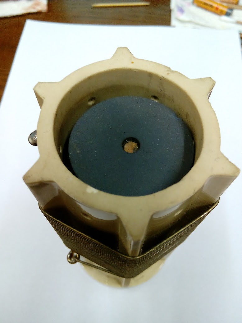
Looks really nice. What's the purpose of the ring around the base
of the choke? I have not seen that before. ## My guess is to shift one of the series resonance freqs. I have
seen a similar trick used before, where a snug fitting copper band
(3/8" to 1/2" tall) was slid up / down the entire length of the
winding, to shift the series resonance freqs.
His ring might be to disperse coronas / extremely high RF voltages.
## I'm well aware of enamel / formvar /nyclad etc, etc. There is
magnet wire....and there is magnet wire. Typ, you can buy magnet
wire in 4 x different thickness of insulation. You can get several
different temp ratings...and also several different voltage ratings,
so beware. I have 8 ga magnet wire, that uses polyimide insulation,
rated for 15 kv and 200 deg C....( but that 15 kv rating is only on
the larger gauges, like 8-10-12-14-16 ga). You can also get
polyester polyimide insulation, rated at 225 deg C. That was the big
problem with folks trying to duplicate existing designs, like the
ameritron choke. With 4 x different thickness's available, that will
change the interwinding C....and shift the series resonance freqs. The
dielectric constant will also change series resonance freqs.
## The belden 22 ga, silver plated / stranded teflon wire I used has
.016" thick insulation. It sez on the spool, it can be immersed into
gasoline ! ARRL book sez teflon is good for at least 2 kv per .001"
(.001" = 1 mil). Web sez, typ it's 1.5 kv per mil. .016 = 16 mils.
At 2 kv per mil, it should be good for 32 kv...( AND 64 KV BETWEEN
TURNS). Even at 1.5 kv per mil, it's good for 24 kv..... and double
any of that, when going from turn to turn. Ec
## I will test that concept with my new 0-15 kvdc hi-pot tester. I
will test between strands in the inside, vs a grnd plane it lays on.
Even AT 1 KV PER MIL IT'S STILL 16 KV ( AND 32 KV BETWEEN TURNS).
## Reid might not have had success with ferrite, but other's like
floyd have. I think the secret is the use of hollow beads...vs a
solid rod.
Links:
------
[1] /g/ham-amplifiers/message/40214
[2] /mt/104281887/8135091
[3] /g/ham-amplifiers/post
[4] /g/ham-amplifiers/editsub/8135091
[5] /g/ham-amplifiers/leave/12941173/8135091/773995006/xyzzy
|
Re: Loaded Plate chokes...again
On Thu, Feb 15, 2024 at 04:59 PM, W7WRX wrote:
Looks really nice.? ?What's the purpose of the ring around the base of the choke?? I have not seen that before.
?
## My guess is to shift one of the series resonance freqs.? ?I have seen a similar trick used before, where a snug fitting copper band (3/8" to 1/2" tall)? was slid? up / down the entire length of the winding, to shift the series resonance freqs.?
His ring might be to disperse coronas /? extremely high? RF voltages.?
?
## I'm well aware of enamel / formvar /nyclad etc, etc.? There is magnet wire....and there is magnet wire.? Typ,? you can buy magnet wire in 4 x different thickness of insulation.? You can get several different temp ratings...and also several different voltage ratings, so beware.? ?I have 8 ga magnet wire, that uses polyimide insulation, rated for 15 kv and 200 deg C....( but that 15 kv rating is only on the larger gauges, like 8-10-12-14-16 ga).? ?You can also get polyester polyimide insulation, rated at 225 deg C.? That was the big problem with folks trying to duplicate existing designs, like the ameritron choke.? ?With 4 x different thickness's available, that will change the interwinding C....and shift the series resonance freqs. The dielectric constant will also change series resonance freqs.?
?
##? The belden 22 ga, silver plated / stranded teflon wire I used has .016" thick insulation. It sez on the spool, it can be immersed into gasoline !? ? ARRL book sez teflon is good for at least 2 kv per .001" (.001" = 1 mil).? Web sez, typ it's 1.5 kv per mil.? ?.016 = 16 mils.? At 2 kv per mil, it should be good for? 32 kv...( AND 64 KV BETWEEN TURNS).? ?Even at 1.5 kv per mil, it's good for 24 kv..... and double any of that, when going from turn to turn.? ?Ec
##? I will test that concept with my new 0-15 kvdc? hi-pot tester.? I will test between strands in the inside, vs a grnd plane it lays on. Even? AT 1 KV PER MIL IT'S STILL 16 KV ( AND 32 KV BETWEEN TURNS).?
## Reid might not have had success with ferrite, but other's like floyd have.? ?I think the secret is the use of hollow beads...vs a solid rod.?
|
Re: Loaded Plate chokes...again
Looks really nice.? ?What's the purpose of the ring around the base of the choke?? I have not seen that before.
toggle quoted message
Show quoted text
I've been in and out and read this thread with some interest.?
My bets are the ferrite loaded chokes will ultimately fail in service (ie. 4CX15,000, 3CX10,000 and similar)
I guess the mention of ole Rich Measures makes me wanna pipe in on this subject, the nutcase that he was... (another story for another day)
anyhow I made plate chokes several years ago after one of the "commercial" hammyfied ferrite loaded chokes blew up and melted down.
Did some experiments using none other than a grid dip meter and buying Teflon by the yard.?
Does the source of Teflon matter? Yes absolutely Industrial grade. Unspecified Teflon can be (is) lossy.?
Does the type of wire matter, yes. Formvar please.
Does the type of Formvar matter yes if you want repeatability.? it comes in different temperature ratings.
I rebuilt most of (the critical parts) of W6CCP's Henry amplifier.? 3CX3000A7 P.O.C.
Attached is a pic of the second choke I had to add to make it perfect, note the small vac relay.
If I had access to a lathe again I would make a few of these.
but they wouldn't be FS to CB'ers. my notes tell why
Very 73,? ?Reid? W6MTF??
from my notes,? ? Series resonances: major at 26.95 minor at 17.2MHz
One series at 34.5MHz. Parallel resonance at 29.0 +/- the proximity to metal.
Total inductance 125uH using #20 AWG high temp Formvar? ??
|
Re: 8410/9500 Wattmeter Failure
Oops, fat fingers... no, it was on 7025, 40m.
Steve, K0XP
On 2/15/2024 6:14 AM, Bob wrote:
Thirty meters? 1150w?
Bob W4JFA?
On Wed, Feb 14, 2024, 8:18 PM
Steve < k0xp@...>
wrote:
If they are the ones in the wattmeter bridge circuit,
they're 1N5711, a fairly common Schottky diode that I've
used before (and may even have some in my stash). They
used to be available everywhere, I dunno about now, I'll
hafta look.
I just chased 8R7X on 30m and am pushing it to 1150W
output; and lo and behold, the very first reflected LED is
popping up dimly but reliably at that output power and
frequency; no others, just that one. I've decided I really
don't like this scheme of using LEDs as a meter; they just
don't seem to give very reliable information all the time
even if they're much cheaper to implement.
Mine seemed to fail either when I turned it off this
morning, or when I turned it back on after a couple hours
(or possibly in-between??). I didn't disturb any coaxes in
between those times, just snuck off and took a nap for a
couple hours after chasing early morning Asian DX. And
this happens when I come back... We had clear skies and
very little but high cloud up there at all. Humidity
perhaps around 30% or so, temp around 40 degs F when I
turned it back on. Odd. I really hate to drag it out to
remove the cover and poke around when I don't yet know
what, specifically, to look at, because this thing is so
heavy and big that I'll have to lug it across the room to
get access to all 19 of the screws, then lug it back to
plug in and try it again. Maybe I'll do that just to try
reseating all the Berg connectors, in the hope...? And I
need to check what the 22-ohm cathode resistors are on
mine, anyway... I don't think mine has had Glenn's
(George??) upgrade to three resistors per tube installed.
AFTER the DX contest, of course? 8-D
Steve, K0XP
On 2/14/2024 4:07 PM, Al wrote:
?Hi Steve,
                 My 8410 took static hit just before Covid started. I talked to Alpha just before they went silent and the sampling diodes are known to blow under your and my conditions. I am currently traveling so I can’t give you the diode numbers but you will find them on the schematic. Like yours mine has full output power but no power out display. With the diodes blown the computer interface has nothing to read. I could not find diodes during Covid hopefully you will have better luck. Let me know how you make out.
73 Allen N3JOC
On Feb 14, 2024, at 10:44 AM, Steve <k0xp@...> wrote:
?I have an 8410; however, according to the schematic(s), it appears as if
it probly uses the same wattmeter as the 9500.

The other day, I encountered intermittent flashover in my external
antenna tuner while running around 1100 watts on 160; it would cause all
the reflected power LEDs on my 8410 to light up. I managed to finish
working someone, let the amp cool down for five mins, then shut it down.
All front panel indicators appeared to work properly at that time
(although I've never, ever, seen a grid current LED light up, nor the
FAULT LED even though I once did have a real fault where I thought that
LED SHOULD light... but it didn't). The output power and reflected power
indicators have always been very accurate and worked fine.

Later that day, I fired it up again... and was chagrined to find NO
output power indicated on the front panel LEDs... neither forward nor
reverse. But the amp was still amplifying normally; output power on an
external wattmeter indicated full power out. I fired up the AE9K Alpha
Monitor program and it, too, shows no output power. But the amp does
still have full output power; so something common to both forward and
reverse power that drives the front panel display failed in my amp. When
the tuner flashed over, my external LP-100A power meter usually
indicated something really high like over 2500 watts momentarily.. once,
I think I saw 2932 watts indicated  ===8-O  Since then, I've fixed the
tuner problem... but have no output power indication on either the
amplifier front panel, nor with the AE9K Alpha Monitor program, even
though the amp is actually still correctly putting out full power.

I'm now printing out all 19 pages of the schematics, but an eyeball
perusal in Acrobat hasn't yet identified exactly which connector carries
the output of the tube deck to the TR system and what it plugs into on
another schematic page. Meanwhile, I thought I'd ask here, in case
someone else has already "invented the wheel" and fixed this kind of
problem. Any help?

TNX,

Steve K0XP
--
See my QRZ.com page at
--
See my QRZ.com page at
|
Re: 8410/9500 Wattmeter Failure
Thirty meters? 1150w? Bob W4JFA?
On Wed, Feb 14, 2024, 8:18 PM Steve < k0xp@...> wrote:
If they are the ones in the wattmeter bridge circuit, they're
1N5711, a fairly common Schottky diode that I've used before (and
may even have some in my stash). They used to be available
everywhere, I dunno about now, I'll hafta look.
I just chased 8R7X on 30m and am pushing it to 1150W output; and
lo and behold, the very first reflected LED is popping up dimly
but reliably at that output power and frequency; no others, just
that one. I've decided I really don't like this scheme of using
LEDs as a meter; they just don't seem to give very reliable
information all the time even if they're much cheaper to
implement.
Mine seemed to fail either when I turned it off this morning, or
when I turned it back on after a couple hours (or possibly
in-between??). I didn't disturb any coaxes in between those times,
just snuck off and took a nap for a couple hours after chasing
early morning Asian DX. And this happens when I come back... We
had clear skies and very little but high cloud up there at all.
Humidity perhaps around 30% or so, temp around 40 degs F when I
turned it back on. Odd. I really hate to drag it out to remove the
cover and poke around when I don't yet know what, specifically, to
look at, because this thing is so heavy and big that I'll have to
lug it across the room to get access to all 19 of the screws, then
lug it back to plug in and try it again. Maybe I'll do that just
to try reseating all the Berg connectors, in the hope...? And I
need to check what the 22-ohm cathode resistors are on mine,
anyway... I don't think mine has had Glenn's (George??) upgrade to
three resistors per tube installed.
AFTER the DX contest, of course? 8-D
Steve, K0XP
On 2/14/2024 4:07 PM, Al wrote:
?Hi Steve,
                 My 8410 took static hit just before Covid started. I talked to Alpha just before they went silent and the sampling diodes are known to blow under your and my conditions. I am currently traveling so I can’t give you the diode numbers but you will find them on the schematic. Like yours mine has full output power but no power out display. With the diodes blown the computer interface has nothing to read. I could not find diodes during Covid hopefully you will have better luck. Let me know how you make out.
73 Allen N3JOC
On Feb 14, 2024, at 10:44 AM, Steve <k0xp@...> wrote:
?I have an 8410; however, according to the schematic(s), it appears as if
it probly uses the same wattmeter as the 9500.

The other day, I encountered intermittent flashover in my external
antenna tuner while running around 1100 watts on 160; it would cause all
the reflected power LEDs on my 8410 to light up. I managed to finish
working someone, let the amp cool down for five mins, then shut it down.
All front panel indicators appeared to work properly at that time
(although I've never, ever, seen a grid current LED light up, nor the
FAULT LED even though I once did have a real fault where I thought that
LED SHOULD light... but it didn't). The output power and reflected power
indicators have always been very accurate and worked fine.

Later that day, I fired it up again... and was chagrined to find NO
output power indicated on the front panel LEDs... neither forward nor
reverse. But the amp was still amplifying normally; output power on an
external wattmeter indicated full power out. I fired up the AE9K Alpha
Monitor program and it, too, shows no output power. But the amp does
still have full output power; so something common to both forward and
reverse power that drives the front panel display failed in my amp. When
the tuner flashed over, my external LP-100A power meter usually
indicated something really high like over 2500 watts momentarily.. once,
I think I saw 2932 watts indicated  ===8-O  Since then, I've fixed the
tuner problem... but have no output power indication on either the
amplifier front panel, nor with the AE9K Alpha Monitor program, even
though the amp is actually still correctly putting out full power.

I'm now printing out all 19 pages of the schematics, but an eyeball
perusal in Acrobat hasn't yet identified exactly which connector carries
the output of the tube deck to the TR system and what it plugs into on
another schematic page. Meanwhile, I thought I'd ask here, in case
someone else has already "invented the wheel" and fixed this kind of
problem. Any help?

TNX,

Steve K0XP
--
See my QRZ.com page at
|
Re: 8410/9500 Wattmeter Failure
Glen AE0Q is the expert on those amps. He's on qrz and also e-ham all the time.? He mentioned those didoes several times over the last 2 years...and also recently.?
|
Re: Loaded Plate chokes...again
I've been in and out and read this thread with some interest.? My bets are the ferrite loaded chokes will ultimately fail in service (ie. 4CX15,000, 3CX10,000 and similar) I guess the mention of ole Rich Measures makes me wanna pipe in on this subject, the nutcase that he was... (another story for another day) anyhow I made plate chokes several years ago after one of the "commercial" hammyfied ferrite loaded chokes blew up and melted down. Did some experiments using none other than a grid dip meter and buying Teflon by the yard.? Does the source of Teflon matter? Yes absolutely Industrial grade. Unspecified Teflon can be (is) lossy.? Does the type of wire matter, yes. Formvar please. Does the type of Formvar matter yes if you want repeatability.? it comes in different temperature ratings. I rebuilt most of (the critical parts) of W6CCP's Henry amplifier.? 3CX3000A7 P.O.C. Attached is a pic of the second choke I had to add to make it perfect, note the small vac relay. If I had access to a lathe again I would make a few of these. but they wouldn't be FS to CB'ers. my notes tell why Very 73,? ?Reid? W6MTF?? from my notes,? ? Series resonances: major at 26.95 minor at 17.2MHz
One series at 34.5MHz. Parallel resonance at 29.0 +/- the proximity to metal.
Total inductance 125uH using #20 AWG high temp Formvar? ??
|
Re: 8410/9500 Wattmeter Failure
If they are the ones in the wattmeter bridge circuit, they're
1N5711, a fairly common Schottky diode that I've used before (and
may even have some in my stash). They used to be available
everywhere, I dunno about now, I'll hafta look.
I just chased 8R7X on 30m and am pushing it to 1150W output; and
lo and behold, the very first reflected LED is popping up dimly
but reliably at that output power and frequency; no others, just
that one. I've decided I really don't like this scheme of using
LEDs as a meter; they just don't seem to give very reliable
information all the time even if they're much cheaper to
implement.
Mine seemed to fail either when I turned it off this morning, or
when I turned it back on after a couple hours (or possibly
in-between??). I didn't disturb any coaxes in between those times,
just snuck off and took a nap for a couple hours after chasing
early morning Asian DX. And this happens when I come back... We
had clear skies and very little but high cloud up there at all.
Humidity perhaps around 30% or so, temp around 40 degs F when I
turned it back on. Odd. I really hate to drag it out to remove the
cover and poke around when I don't yet know what, specifically, to
look at, because this thing is so heavy and big that I'll have to
lug it across the room to get access to all 19 of the screws, then
lug it back to plug in and try it again. Maybe I'll do that just
to try reseating all the Berg connectors, in the hope...? And I
need to check what the 22-ohm cathode resistors are on mine,
anyway... I don't think mine has had Glenn's (George??) upgrade to
three resistors per tube installed.
AFTER the DX contest, of course? 8-D
Steve, K0XP
On 2/14/2024 4:07 PM, Al wrote:
?Hi Steve,
                 My 8410 took static hit just before Covid started. I talked to Alpha just before they went silent and the sampling diodes are known to blow under your and my conditions. I am currently traveling so I can’t give you the diode numbers but you will find them on the schematic. Like yours mine has full output power but no power out display. With the diodes blown the computer interface has nothing to read. I could not find diodes during Covid hopefully you will have better luck. Let me know how you make out.
73 Allen N3JOC
On Feb 14, 2024, at 10:44 AM, Steve <k0xp@...> wrote:
?I have an 8410; however, according to the schematic(s), it appears as if
it probly uses the same wattmeter as the 9500.

The other day, I encountered intermittent flashover in my external
antenna tuner while running around 1100 watts on 160; it would cause all
the reflected power LEDs on my 8410 to light up. I managed to finish
working someone, let the amp cool down for five mins, then shut it down.
All front panel indicators appeared to work properly at that time
(although I've never, ever, seen a grid current LED light up, nor the
FAULT LED even though I once did have a real fault where I thought that
LED SHOULD light... but it didn't). The output power and reflected power
indicators have always been very accurate and worked fine.

Later that day, I fired it up again... and was chagrined to find NO
output power indicated on the front panel LEDs... neither forward nor
reverse. But the amp was still amplifying normally; output power on an
external wattmeter indicated full power out. I fired up the AE9K Alpha
Monitor program and it, too, shows no output power. But the amp does
still have full output power; so something common to both forward and
reverse power that drives the front panel display failed in my amp. When
the tuner flashed over, my external LP-100A power meter usually
indicated something really high like over 2500 watts momentarily.. once,
I think I saw 2932 watts indicated  ===8-O  Since then, I've fixed the
tuner problem... but have no output power indication on either the
amplifier front panel, nor with the AE9K Alpha Monitor program, even
though the amp is actually still correctly putting out full power.

I'm now printing out all 19 pages of the schematics, but an eyeball
perusal in Acrobat hasn't yet identified exactly which connector carries
the output of the tube deck to the TR system and what it plugs into on
another schematic page. Meanwhile, I thought I'd ask here, in case
someone else has already "invented the wheel" and fixed this kind of
problem. Any help?

TNX,

Steve K0XP
--
See my QRZ.com page at
|
Re: 8410/9500 Wattmeter Failure
?Hi Steve,
My 8410 took static hit just before Covid started. I talked to Alpha just before they went silent and the sampling diodes are known to blow under your and my conditions. I am currently traveling so I can’t give you the diode numbers but you will find them on the schematic. Like yours mine has full output power but no power out display. With the diodes blown the computer interface has nothing to read. I could not find diodes during Covid hopefully you will have better luck. Let me know how you make out.
73 Allen N3JOC
toggle quoted message
Show quoted text
On Feb 14, 2024, at 10:44 AM, Steve <k0xp@...> wrote:
?I have an 8410; however, according to the schematic(s), it appears as if
it probly uses the same wattmeter as the 9500.
The other day, I encountered intermittent flashover in my external
antenna tuner while running around 1100 watts on 160; it would cause all
the reflected power LEDs on my 8410 to light up. I managed to finish
working someone, let the amp cool down for five mins, then shut it down.
All front panel indicators appeared to work properly at that time
(although I've never, ever, seen a grid current LED light up, nor the
FAULT LED even though I once did have a real fault where I thought that
LED SHOULD light... but it didn't). The output power and reflected power
indicators have always been very accurate and worked fine.
Later that day, I fired it up again... and was chagrined to find NO
output power indicated on the front panel LEDs... neither forward nor
reverse. But the amp was still amplifying normally; output power on an
external wattmeter indicated full power out. I fired up the AE9K Alpha
Monitor program and it, too, shows no output power. But the amp does
still have full output power; so something common to both forward and
reverse power that drives the front panel display failed in my amp. When
the tuner flashed over, my external LP-100A power meter usually
indicated something really high like over 2500 watts momentarily.. once,
I think I saw 2932 watts indicated ===8-O Since then, I've fixed the
tuner problem... but have no output power indication on either the
amplifier front panel, nor with the AE9K Alpha Monitor program, even
though the amp is actually still correctly putting out full power.
I'm now printing out all 19 pages of the schematics, but an eyeball
perusal in Acrobat hasn't yet identified exactly which connector carries
the output of the tube deck to the TR system and what it plugs into on
another schematic page. Meanwhile, I thought I'd ask here, in case
someone else has already "invented the wheel" and fixed this kind of
problem. Any help?
TNX,
Steve K0XP
|
